


.jpg "TEAM: Probot")


Analog Computer Creation by Levitating Potato
March 7th, 2008 8:31 PMIntroduction
There are lots of ways one could build an analog computer; I decided to take a traditional approach, using relatively simple analog electronics. So, armed with a couple amplifier chips, a handful of resistors and capacitors, and a lightbulb, I went to work.
I needed an interesting problem to solve; I thought about several different ideas before finding one I really liked. I never did calculate Pi, so this task seemed the perfect time to do so. The usual formulas for Pi are all long, complex sums -- something analog computers have trouble with. I needed an approach that was uniquely suited to the analog world.
Pi shows up in a range of formulas for analog circuit work, usually in relation to sine waves. All that remained was to create a sine wave, and process it in such a way that I could tease Pi out of the formulas that are its customary habitat.
Circuit outline
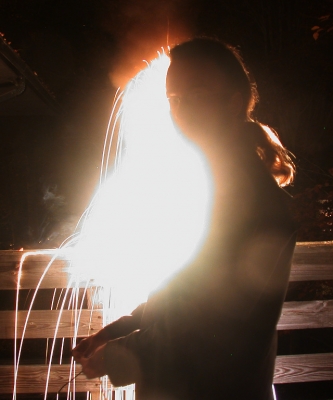
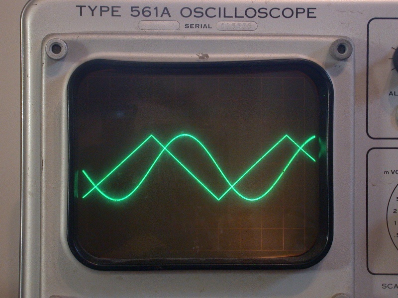
Recalling a (small! I promise!) amount of calculus accomplishes the task. First, I create two signals -- one a sine wave (this is where the lightbulb comes in), the second a triangle wave. Specifically, I generate them in such a way that they have exactly the same frequency (by using the sine wave to generate the triangle wave), and then adjust the amplitude of the triangle wave until the peak values of both are exactly the same.
Looking at half a cycle of each wave, centered at t = 0, we have sin(-pi/2) = -1 and tri(-pi/2) = -1, and also sin(pi/2) = 1 and tri(pi/2) = 1 (normalized for simplicity; there are additional constants in the actual circuit but the math is unchanged). The triangle wave is a straight line, so its slope for the entire interval is (y2-y1)/(t2-t1) = (2/pi). Since the derivative of the sine is the cosine (that's it; I promised there wouldn't be much calculus), the slope of the sine wave at t=0 is 1 (this is also its maximum slope, which is important to the details of the circuit operation). These two slopes differ by a factor of pi/2, so all that remains is to adjust the constants until the triangle wave has a slope of 2, and read off the slope of the sine wave to get Pi. (Or, if you'd rather, treat the circuit output as the ratio of the two outputs.)
The most interesting part of all this, I think, is that with a small amount of tuning a good result is obtainable without any precision components. Of course, that is precisely the goal --we're calculating Pi, a mathematical constant that is intimately involved in the circuit operation, not simply the number 3.14.
Circuit details
For those that are curious, I'll briefly discuss the details of the circuit. If you're not interested, feel free to skip ahead to the pictures.
The circuit is based around op amps, which provide an incredibly versatile building block. Wikipedia also has discussions of the individual configurations.
U1, a 741 type op amp, is configured as a Wien bridge oscillator. This classic circuit does an excellent job of producing a wave form that is precisely sinusoidal. The problem with a Wien bridge, as with any sinusoidal oscillator, is providing gain control. Too much gain, and the oscillation grows until it is overdriving the amplifier, which results in distortion. Too little gain, and the oscillation decays to zero. The solution is elegantly simple -- a light bulb. The bulb's resistance increases as its temperature increases, which reduces the gain. As the magnitude of the oscillation grows, the power into the light bulb grows as well, raising its temperature. Since the light bulb is slow to respond (compared to the speed of the oscillator), it provides almost completely distortion-free gain limiting. Some trivial changes to the circuit (namely, replacing the 741 with a better op amp) would produce a sine wave worthy of audio test equipment -- about 0.0015% distortion with no other changes.
U2A is a simple LM339 comparator, used to detect the zero-crossing of the sine wave. When the sine wave is positive, its output is high; when negative, it's low. This provides a square wave of almost precisely 50% duty cycle and of exactly the same frequency as the sine wave input. U3A is a simple voltage buffer, providing a low impedance output to ensure a clean square wave.
U3A is an AC-coupled voltage follower; it centers the square wave around zero and provides output capability so that the integrator doesn't induce distortion in the square wave.
U3B is configured as an integrator. The integral of a square wave is a triangle wave; the 90 degree phase shift is irrelevant here. The largest sources of error in the triangle wave shape are probably from imperfections in the square wave duty cycle due to comparator offset voltage and asymmetry; I don't actually have the test equipment to tell, though.
U3C is a differentiator; it can be connected to either the sine wave or triangle wave output in order to provide the slopes of the two curves. By using the same components and changing the connection, rather than building two differentiators, I remove component tolerances in the differentiator circuit as a source of error.
U2B is a peak detector. It is connected alternately to the sine wave and triangle wave outputs in order to measure peak amplitude of the two waveforms so they can be adjusted to equal amplitude. It is then connected to the differentiator output in order to measure the maximum slope of the sine and triangle waves, which are the values of interest. One detector with varied connections is used for the same reason as in the differentiator.
U2 is an LT1014A precision op amp; selection was limited by what I had on hand, and the cheap quad op amp (an LM324) introduced too much distortion. A better choice would be a faster op amp -- U2A actually has a slightly trapezoidal output, because it can't keep up with the square wave transitions.
Note that the schematic presented is lacking some details -- notably the scale trims for the integrator (triangle wave amplitude trim) and slope detector (to trip the absolute outputs to 2 and Pi, rather than some arbitrary other values with the same Pi/2 ratio), and the integrator zero trim.
Oh, and the power supplies I used for this circuit are the same foot-crushingly heavy ones I've mentioned before.


31 vote(s)
- teucer
- Lincøln
- susy derkins
- Spidere
- Sean Mahan
- Tøm
- .thatskarobot
- GYØ Ben
- Burn Unit
- Jellybean of Thark
- anna one
- Tricia Tanaka
- Loki
- Ben Yamiin
- Cameron
- Fonne Tayne
- Optical Dave
- avidd opolis
- rongo rongo
- HKEY_Current _User
- inquisitive dragonfly
- Lizard Boy
- Haberley Mead
- scotbotmosh
- help im a bear
- H L
- Rao
- Tac Haberdash
- kurtis
- Sam Archer
- Idøntity matrix
Favorite of:
Terms
electronic, analog, oscilloscope10 comment(s)

It´s mostly like Russian to me, but did you ever saw "A Fish called Wanda"?

I did, but it's been at least 10 years, so I can't claim to remember it well. Why do you ask?
My hope was that the math (ie why the slopes of the waveforms have a ratio of Pi/2) would be accessible to anyone who vaguely remembered calculus class, and that the electronics would be to anyone who had worked with op amps or felt like spending a few hours staring at the Wikipedia pages -- though I don't really expect anyone to do that :)
Oh, just that even though Wanda didn´t understand Russian she still loved it :)
The bulb's resistance increases as its temperature increases, which reduces the gain. That sentence and its implications I understood and gave me the good ol´ feeling of nerdy realization of another instance proving that the workings of the clockwork are indeed awesome (you now, the feeling that causes shiny, wide opened eyes for at least five minutes).
Try whispering "U1, a 741 type op amp, is configured as a Wien bridge oscillator. The problem with a Wien bridge, as with any sinusoidal oscillator, is providing gain control" to a girl sometime, steamy!
Yes, I know that feeling well...
I've found that light bulb oscillator circuit to be a thing of elegance since I first encountered it, perhaps a year or so ago. Especially the fact that trying to replace the lightbulb with something "better" takes the circuit from 7 components total to being a full page schematic.
The circuit was taken from an application note written by Jim Williams (who I'm sure would be horrified that I used a noisy, high-distortion 741 in it -- but I had it in the cabinet). He describes the circuit as "a modern adaptation of one described by a Stanford University student, William R Hewlett[4] in his 1939 master's thesis." Footnote 4 informs us that "History records that Hewlett and his friend David Packard made a number of these type oscillators. Then they built some other kinds of instruments."

and that the rest (those who didn't take calculus or are going to spend their wiki-hours staring at other pages) will simply take it on faith that it's awesome. Let me be the first to say I do.

I've got a vague sense of understanding for what's happening here. Just enough for it to click in my head and feel the outline of this particular awesome.
Well done.


Nice! Though I admit I didn't read all the technical details, the gestalt alone was impressive.

Awesome.
I spotted scope screen in the random pictures just as I had clicked off the page.When I went back, it had changed. I reloaded about 50 times watching for the random picture that had captured my attention. Finally the bulb came on to search oscilloscope and voila
Awesome.
Pi is actually 3.44827586.