75 + 10 points
Stayin' Alive by Selahsaurus
September 19th, 2010 11:48 AM
I am PREPARED for end of days. Non perishables? Check. Months worth of water? Check. Weapons? Oh boy, CHECK! Shelter? Check. Means of immediate, emergency escape? Check, and check.
Survival will not be a problem for me and my family. Living though? Well, that's an entirely different story. So I thought to myself. What makes my life most comfortable right now, where there is no immediate threat. Well, the internet, but besides that... electricity.
So how does one go about creating electricity, or powering a generator, when all the power lines go out?
I decided to learn how to create wood fuel.
Fuel gas, produced by the reduction of coal and peat, was used for heating as early as 1840 in Europe and by 1884 had been adapted to fuel engines in England. Prior to 1940, gas generator units were a familiar, but not extensively utilized, technology. However, petroleum shortages during World War II led to widespread gas generator applications in the transportation industries of Western Europe. (Charcoal burning taxis, a related application, were still common in Korea as late as 1970.) The United States, never faced with such prolonged or severe oil shortages, has lagged far behind Europe and the Orient in familiarity with and application of this technology. However, a catastrophic event could disrupt the supply of petroleum so severely that this technology might be critical in meeting the energy needs of some essential economic activities, such as the production and distribution of food.
Harvest Power employs evolutionary gasification technology to convert wood waste and other feedstocks into renewable syngas ideal for producing electricity, heat, and substitute natural gas. Wood gasification sounds like a fancy technique, but this process has been used to create fuel since before WWII–people get creative during dire energy shortages.
Here's a really cool example of a guy who converted his volvo to run off of wood fumes:
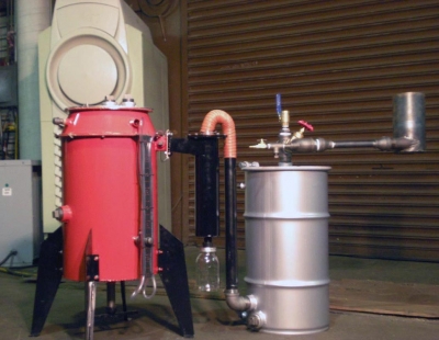
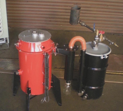
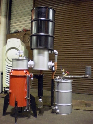
Ok. So I have done my research. Now. To learn how to ACTUALLY put my knowledge to good use and actually BUILD one of these bad boys!
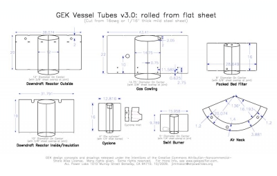
PDF Blue Prints and Instructions
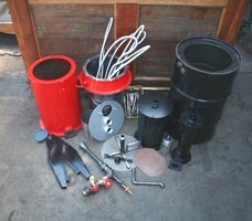
We are a go!
Plumbing Box
Description Part Type Quantity
0.375" black cap, drilled Black Plumbing 5
0.5" black nipple, 6" long Black Plumbing 5
0.5" - 1/4 reducing bushing Black Plumbing 3
0.5" black cap Black Plumbing 2
0.5" black elbow Black Plumbing 2
0.5" black nipple, 3.5" long Black Plumbing 2
0.5" black plug Black Plumbing 4
0.5" black tee Black Plumbing 2
1.5” elbow Black Plumbing 1
1.5” close nipple Black Plumbing 1
1.5" black plug Black Plumbing 3
0.5" - 1/4 reducing bushing Black Plumbing 2
0.5" black nipple, 7" long Black Plumbing 1
1" black cap Black Plumbing 1
2" black plug Black Plumbing 1
Ejector Box
Description Part Type Quantity
0.5" black nipple, 2 long, THREADED Black Plumbing- Eturi 1
0.5" black plug Black Plumbing- Eturi 1
0.5" black tee Black Plumbing- Eturi 1
0.5" to 1/4" reducing bushing Black Plumbing- Eturi 1
0.75" ball valve Black Plumbing- Eturi 1
0.75" black nipple, close Black Plumbing- Eturi 1
0.75" x 6" black nipple Black Plumbing- Eturi 1
1.5" black close nipple Black Plumbing- Eturi 4
1.5" black cross Black Plumbing- Eturi 1
1.5" black plug Black Plumbing- Eturi 1
1.5" gate valve Black Plumbing- Eturi 1
1.5" to 3/4" black reducing bell Black Plumbing- Eturi 2
1.5" to 3/4" black reducing bushing Black Plumbing- Eturi 1
1.5" x 1/2" x 1.5" black reducing tee Black Plumbing- Eturi 1
1/4" air quick connect (m/m) Black Plumbing- Eturi 1
1/4" ball or needle valve Black Plumbing- Eturi 1
3/8" black nipple 4" or 4.5"THREADED Black Plumbing- Eturi 1
brass barb 1/4 npt x 1/8 barb Black Plumbing- Eturi 1
Hopper Barrel
Description Part Type Quantity
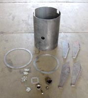
30 gal hopper assembly Fab Metal Parts 1
reactor lid Fab Metal Parts 1
gas cowling assembly Fab Metal Parts 1
gas cowling ss insulation tube CNC Cut Parts 1
ash grate assembly Fab Metal Parts 1
reactor assembly Fab Metal Parts 1
SS Reactor insulation sleeve CNC Cut Parts 1
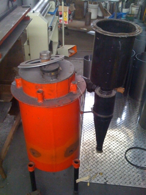
cyclone assembly Fab Metal Parts 1
cyclone tube and flange ring Fab Metal Parts 1
nozzles Fab Metal Parts 5
monorator ring Fab Metal Parts 1
reactor taper CNC Cut Parts 1
hopper taper CNC Cut Parts 1
Filter Barrel
Description Part Type Quantity
filter perf disk, 13 7/8" diameter CNC Cut Parts 1
gas cowling ash port cover Fab Metal Parts 1
reactor port lid cover CNC Cut Parts 1
rocket legs Fab Metal Parts 4
swirl burner Fab Metal Parts 1
1" wide ceramic gasket strip Hardware 1
gas cowling insulation sheet Hardware 1
mason jar Hardware 1
CO meter Instrumentation 1
moisture meter Instrumentation 1
1/4" npt - 1/4" barb Other Plumbing 2
dual thermo reader Instrumentation 1
18" type K probe Instrumentation 1
12" type K probe Instrumentation 1
pvc hose Instrumentation 2
manometer Instrumentation 1
1.5" close nipple Plumbing 1
1.5" elbow Plumbing 1
16" of silicone flex hose Other Plumbing 1
fuel feed taper; hopper (3 pieces)Manual cut part 1
SS 3/4"x72" gas conn. w adapters Other Plumbing5
24" x 2" chimney for filter Fab Metal Parts 1
Ash shake handle Other Hardware 1
Mason ring Fab Metal Parts 1
clay weatherstripping Other Plumbing 1
Reduction Bell Fab Metal Parts 1
High temp mortar Hardware 1
plumbing box pre pull packing 1
ejector box pre pull packing 1
hardware box pre pull packing 1
filter barrel and lid 1
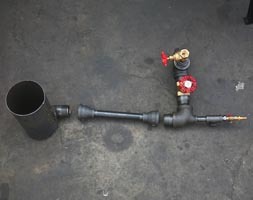
Inventory for building the ejector venturi
PART TYPE
#
1.5" black cross 1
1.5" black plug 1
1.5" black close nipple 4
1.5" x 1.5" x 1/2" black reducing tee 1
1.5" to 3/4" black reducing bell 2
0.75" x 8" black nipple 1
1.5" gate valve 1
0.75" ball or gate valve for air mix 1
1/4" ball or needle valve for air drive 1
1.5" to 3/4" black reducing bushing 1
0.75" black nipple, close 1
0.5" black nipple, 2 long, INSIDE THREADED 1
0.5" black tee 1
0.5" black plug 1
0.5" to 1/4" reducing bushing 1
1/4" air quick connect (m or f ? ) 1
3/8" black nipple, 4" /4.5" INSIDE THREADED 1
brass bard 1/4 npt x 1/8 barb 2
1.5" black nipple, 6" long 1
1/4" black nipple, close 1
1/4" npt x 1/8" brass barb 1
Hardware Box
Description Part Type Quantity
5/16 wing nuts Hardware 10
5/16 x 1.5" bolts for puff lids Hardware 2
1/2” to 1/8” Bushing Hardware 2
Screws for hopper taper Hardware 10
1/2” to 1/2” compression fitting drilled Hardware 1
1/4” to 1/8” compression fitting drilled Hardware 2
5/16"x4” All thread bolt for grate posts Hardware 4
box of 5/16 nuts (50 count) Hardware 1
box of 5/16 x ??? bolts (50 count) Hardware 1
brass barb 1/4 npt x 1/8 barb Hardware 2
springs for puff lid Hardware 2
hose clamps Hardware 2
screws for insulation tubes Hardware 9
teflon tape Hardware 1
zip ties Hardware 10
3/8” washer Hardware 8
3/8” rubber washer Hardware 8
3/8” bolts Hardware 4
1/2” lock nut Hardware 1

The Masonic Method uses two temperature and two pressure measurement points to guide all critical operational issues with a downdraft gasifier. The same 4 points are also used to diagnosis common problems with a gasifier as well as guide refinements of nozzle sizing, hearth geometry and fuel specific optimizations. The details on the tuning method will come in a separate post.
The two temperature and pressure measurement points needed are as follows. See also the above graphic.
Temperature 1: Hearth restriction
Temperature 2: Bottom of reduction zone
Pressure 1: Pressure drop across nozzles
Pressure 2: Pressure drop across full reactor (nozzles + bed)
The most helpful gauge for informed gasifier driving is a manometer measuring the pressure drop across the reactor. The pressure drop across the reactor tells you to an approximation how fast you are pulling the reactor-- or in other words, how much gas you are making.
For good results, you need to pull gas between the min and max gas rate acceptable for the gasifier hearth dimensions. Pulling too fast or too slow will create problems.
-Pull too slow and you'll make a mess of tar.
-Pull too fast and you'll make soot, weak gas, and ultimately clinkers.
This min and max gas rate band is fairly narrow, thus the need for an experienced operator to find it. Fortunately we can quantify this "good band" and have the “newbie” read a gauge to approximate "expertise".
Our tests have shown the min-max pull rate band as 2" to 10" of h2o vac across the reactor (before filtering). Stay within these limits and you'll have good results. For even better results, try to stay in the sweet spot,, which we consistently find to be 4-6"h2o vac range. You can push things up to about 12" and idle down to about 1", but you are tempting trouble at these extremes.
Here's these "speedometer" manometer numbers as a chart. You might want to print these out and keep them with your gasifier.
12+: Overpull
10: Maximum
8: OK
6: Good
5: Ideal
4: Good
2: OK
1: Minimum
0-1: Underpull
These values can be read manually via a simple manometer, or we can use the same values to inform idiot lights and electronic automation. In all these cases, the critical new learning here is that we can formalize the min-max rate, and make informed operating decisions in relation. We do not need to guess, nor do we need to rely on years spent face down in the black goo.
These numbers assume a well configured gasifier with reasonable hearth geometry and nozzle sizing. We can get close to reasonable dimensions using the standard Imbert charts. For further refinement of these dimensions and configurations, see the tuning section below.
Yes, different gasifier types, sizes and fuels will introduce some variations in this scale, but they are less than one would fear. Also, these variations can be quantified with the same formal system, and thus compared between machines. Refinements and addenda are expected to the above guidelines as others use it.
Your Gasifier Tachometer
(aka: the thermocouple)
Minimum RPM
Tar cracking in an Imbert type gasifier is achieved through creating a high temp combustion lobe across the full hearth area, and forcing tars to pass through it and crack from the high heat. The goal is to spread cracking adequate temps across the full hearth volume --all the down to the restriction-- and not let any tar pass around the edges, center, or other cool spots.
Full and complete temp PROPAGATION is what is important here, not just high spot temps in front of the nozzles. Actually, the temp in front of the nozzles is somewhat irrelevant. What matters is how well the high temp has filled the entire hearth and propagated all the way to the restriction.
Our hypothesis is that the best way to measure this “fullness of propagation” is the temp achieved at the restriction, NOT the temp right in front of the nozzle. If the nozzles are sized reasonably, and we find some X adequate tar cracking temp still present at the restriction, we can reasonably conclude that the hearth combustion cone is filled with a temp somewhat above this. Tar most likely will be passing through these higher hearth temps, and at the very least will pass through the directly measured temp at the restriction (given the narrow gas passage).
In our recent tests we’ve been very pleased to find there is, in fact, a very strong correlation with temp at the restriction and tar in the output gas. There is a very clear and rather linear relationship between temperature at the restriction and tar cracking success. There is similarly a rather poor relationship between temps right in front of the nozzles and success in tar conversion.
You can see test results on the correspondence between restriction temp and tar conversion here:
http://gekgasifier.pbworks.com/f/1259099233/summary2_tar_s2_v_tredc.png
The takeaway from the tests is that if we have 900c or above at the restriction, tar will disappear “completely” form the output gas. Tar destruction continues to be reasonable down to about 800C at the restriction. Below here tar passing will rise to unacceptable levels.
This gives us a very simple probe point we can monitor in real time to see if we are making tarry gas or not. It is also a somewhat cooler measurement point than the right at the nozzles, thus our thermocouple is less likely to melt. We can use this measurement point and numeric value as a new rule for helping newbies drive a gasifier successfully:
"Always keep the restriction temp above 800C! If you let it go below this, you will have lots of tar in your gas"
Maximum RPM
If a thermocouple at the restriction is your best monitoring point to know when things are too cold, a thermocouple at the end of the reduction zone is your best monitoring point to know when things are too hot.
A thermocouple at the end of your reduction zone tells you how fully your reduction is finishing. Pull too fast and the reduction reactions will not have adequate time to complete. Gas exit temp will rise as a result.
Gas energy density increases the further we run reduction to it lowest temp potential. Also, CO reversion to soot and CO2 increases the higher temp the CO leaves the bed. Run the temps up even higher and the ash will begin to fuse into clinkers. This is the ultimate “redline” point of the gasifier—when you start to make clinkers.
This “redline” RPM of the gasifier appears to be about 900-950C out the reduction bell. Above here I anecdotally notice significantly increased soot production and soot filling the cyclone jar. Go significantly above it and you’ll fill the hearth with clinkers.
Thus we can give the newbie a simple rule to define the max pull rate and temp before things will start melting down.
"Always keep the end of reduction zone temp at or below 900C! If you let it go above this, you will create excess soot, weak gas, and ultimately clinkers that will plug the hearth."
When to Shake the Grate
As the reduction bell gets packed with ash, the resistance to gas flow increases. This will increase the pressure drop across the reactor. At a constant gas flow rate, we can see this as a rising reading on the manometer.
Unfortunately, gas flow rate will also change this reactor vac reading. We need to find a signal that is independent of, or co-varies with changes in gas flow rate. The way we’ve discovered to do this is to monitor the RATIO between the pressure drop across the nozzles and the pressure drop across the bed.
The pressure drop across the nozzles is NOT impacted by variations in bed packing. The pressure drop across the nozzles follows from the nozzle hole size, not anything happening later in the bed. We can measure this with a pressure port somewhere in the reactor around nozzle level, as shown in the graphic above. The pressure drop across the bed is the total reactor pressure drop reading minus the nozzle reading. The total reactor reading is measuring the combination of BOTH the nozzle and bed pressure drops.
Once we know the nozzle and bed pressure drop readings separately, we can find the ratio between them, and this ratio will stay about the same independent of flow rate. Or rather, both of the pressure readings co-vary near proportionally with flow rate changes, thus the ratio between them stays constant. This ratio will only change when the bed packs and the resistance to gas flow through the bed rises.
When the bed is properly purged and gas is flowing well, we like to see at 1:1 ratio between the nozzle drop vs bed drop. Said another way, the nozzle pressure reading should be about 50% of the total reactor pressure reading. (This of course assumes your nozzles are sized correctly in the first place, which is covered below in the tuning section.)
If this ratio changes, we know the bed is packing. Proportionally more pressure drop is coming from the bed than the nozzles. When we see this, we know to shake the grate and restablish the correct ratio. We can use this ratio threshold for manual grate shaking, or as input to an automated grate shaking system. We can most simply read this ratio off a manual visual manometer. Or the computer can read this ratio and respond accordingly via a micro-controller.
1. Air Flow
Open the compressed air valve on the ejector venturi system. This is the 1/4" valve where the air line connects. The monometer should respond easily upwards to 5 inH2O. Set the pressure drop across the reactor to about 3 inches of water. If the monometer does not respond, go back to Final Preparation Before Lighting.
2. Ignition:
Open the air inlet. Squirt in a bit of liquid fuel to start. Light with a propane torch about an inch from the inlet so as to provide oxygen for the propane torch. Make sure that the air is flowing into the reactor to be careful of potential back fire. You may need to keep the torch there for a minute or two. Be sure to close the cap on the ignition port when reactor is lit (and open the 1" air cowling port), and seal it with clay weatherstripping or RTV silicone prior to iginition.
Ignition has been shown to be possible with just a propane torch, with lower flows leading to faster initial ignition. Recommended reactor pressure reading: 1" H2O during ignition.
 3. Flare
Within a few seconds of lighting, gas will come out of the flare. At first this may not be a combustable gas until the reactor gets up to temperature. Be sure to have a manual pilot light or propane torch to help burn off the tar and steam smoke on start up. This will keep a good large pilot flame at where the syngas enters the swirl burner, and keep things clean until the syngas flame will sustain itself. The extra flare will prevent unburned gas from floating around your work area. Get a hand propane torch so you can do this, ideally with piezo-ignition.
If this initial period of uncombusted gases is a concern, propane can also be introduced just before the flare via a pumbing T and turned off after a few minutes of reactor warm up. There is a port that comes with the ejector venturi for this purpose.
4. Sustained Flare
After a few minutes you will be able to turn off your propane pilot light torch on the flare. Adjust the oxygen mixture on the flare to transition from a propane to woodgas flare (this is the 3/4" valve on your ejector). Keep it handy in case the syngas flare goes out and you need to relight it quickly. Remember do not breathe the gas when it is unburned. After it is burned it is very clean.
Notice: When the O2 valve is closed too far, the flare does not have enough oxygen and it will rise up out of the flare stack. Because there may not be enough oxygen to competely combust the carbon monoxide and hydrogen, there could be some carbon monoxide being released near the flare that has not combusted. As you open the O2 valve, the flare will pull back into the flare stack. All of the woodgas should be combusting before halfway along the flare stack. This ensures a complete combustion.
Notice: When the O2 valve is opened the ejector will be pulling air through this port which will lower the vacuum that it pulls on the rest of the system. Notice that when the O2 valve is opened, the manometer will indicate that the pressure drop across the reactor (and the filter) lowers. Make sure that you are staying in range of the proper pull rate. You may need to increase the flow across the ejector to make up for this difference.
5. Proper Gas Pull Rates and Ranges
For starters, we suggest running the reactor at about 5" h2o vac, as read on the GEK manometer. This is a robust pull rate that will ensure tar is converted and the char is burned into configuration quickly.
As for ongoing running, here's the range of gas pull rates you can explore, and where the "out of bounds" thresholds are to be found. Remember this is the reactor only. You can expect to see another 2-5" h2o with the reading after the filter.
10+ Overpull
8 Maximum
6 Good
5 Ideal
4 Good
2 OK
1 Minimum
0-1 Underpull
Overpull creates a mess of soot and weak gas
Underpull creates a mess of tars and richer gas.

10. Filter
The manometer is your first indication that the filter media may be clogged.
If the filter media is working properly, generally there will be a 2-4 inch of water difference between the two of them.

If the reactor and filter pressure have a larger difference between them, it might be best to change your filter media.


11. Note rate of fuel consumption
All biomass is different. Check the fuel level every few minutes through the fill port until you get a feel for how quickly it lowers. Do not let it go more than halfway to the nozzles before you refill. Without a hopper or auger filling option attached, the reactor will likely need more fuel every 5-10 minutes.Nonetheless, when first learning how the GEK runs, you should experiment without the hopper.
I. Convert your engine to run off of wood gas
Running an engine on wood gas requires some relatively minor tweaks to the engine air intake system. With either a gasoline or a diesel engine, you are going to be introducing the wood gas into the stock air intake system. You do not need to create a complicated new carburator like a propane or natural engine. Rather, you just mix the wood gas in with the air on the way in the normal air intake. As the correct wood gas to air mixture ratio is about 1:1 and is very tolerant of error, it is quite easy to get a reasonable mixture with very rough solutions.
The easiest way to make a wood gas mixer is with a plumbing tee and a ball valve (sized appropriately for the enging intake). A tee is put in the air intake pre filter, with one leg of the tee going to the gasifier, and the other going to free air. You install the ball valve on the air side. Mixture is then controlled by opening or shutting this ball valve. To the degree you shut the ball valve, more gas is pulled from the gasifier. To the degree you open the ball valve, more air is pulled from atmosphere.
People usually mount their new wood gas carburetor on the intake to the existing air filter. This will be your last filter before the engine. Some people like to add bigger ones here. But most do fine using what comes stock with the engine.
Here's a few things to consider when attaching your wood gas mixer to your air filter:
* Keep it air tight: Air filter canisters are often far from air tight! (On the Honda Accord, we did not notice an extra unpopulated bolt pattern underneath the canister this was delivering leaner mixtures than our controls indicated which caused problems).
* The extra T fitting and valve will add extra weight to the canister. They are typically not designed to support weight, make sure your design holds up.
* Minimize the amount of mixed fuel/air you have in the system. Place the T for the air mixture connection as close to the air filter canister as possible.
* The air to fuel ratio for wood gas is 1:1. However, the air mixture valve pipe diameter will be smaller than the wood gas line. For the GEK, use the existing 1.5'' wood gas line with a 1'' or 3/4" air mixture ball valve. The vacuum from the engine will more easily pull air in through the air line than wood gas from the gasifier.
* Consider putting the air mixture valve at the end of a longer tube. This is to prevent puffs of CO coming out the air side of your mixer. This is especially important with one cylinder engines. The puffing nature of the intake can send CO out the air side of the mixer
* Put your air into the tee on the perpendicular leg. This helps reduce puffing out the other end. Try to not put the air into the tee so that it has a direct line shot out the open leg. The gasifier and the engine should be on the straight through shot legs. The air on the side leg.
Gasoline Engine Conversion
Carburated Engine
Carburetor gasoline engines are fairly simple to convert. One build a wood gas carburetor like above. The air filter housing is modified so the mixer can attac to it. And the timing is usually advanced 10-15 degrees. Wood gas has a slow flame front, thus you need to advance the timing to maintain reasonable power.
The throttle in the carburetor continues to be used for the speed control. Like with regular gasoline, the mixture is done separately of the butterfly in the carburetor. The butterfly is to control the amount of mixed fuel/air that goes into the engine. We will continue to use it for such, just with the gasoline shut off, and the mixture now done externally with the wood gas mixer.
The mixture will be controlled manually with the ball valve on the air intake side. Usually one tries to start with the valve near closed (or very rich mixture), and slowly open it while cranking. At some point in this slow opening you will cross the correct mixture point and the engine will fire. Then you adjust the valve back and forth until you hone in on the exact mixture.
This valve setting for correct mixture will change with engine speed and load, as well as gas quality out of the gasifier. This is why a fully automated mixture system is desired for regular hands off running. The manual solution is fine if you are sitting there driving a vehicle with wood gas. It is more of a problem with a genset where you are not standing there operating the machine full time.
Fuel Injection Engine
Fuel injected gasoline engines are also good candidates for wood gas conversion. You will still enter the wood gas into the engine via the air intake. Shutting off the gasoline fuel with injectors is faster and more precise than a carburetor. Some ECU systems with fuel injected motors will still correct mixture for you with a small amount of gasoline. Thus you can leave the injectors on and slowly add in wood gas. However, this is somewhat unsatisfying after you've gone to all the work to get your gasifier to work. You usually just want to cut the gasoline altogether.
To cut off the fuel injectors you need to locate the wire delivering power to the fuel injectors (reference the wiring diagram in the manuel for the enigne). Once found, put a switch in the line, ideally mounted somewhere near where you are going to operate the machine. Then you can easily go back and forth between gasoline and syngas at the flip of a switch.
Important: Do NOT just put a valve in the gasoline line. You can ruin your fuel injectors if you run them dry for extended periods. You must cut the power to the injector, NOT the fuel the injectors.
Some contempory ECU units will auto advance the timing for you, via the stock detonation sensor. Some will not. Here you need to get into the wires and diagrams of your own system. Sometimes you need to a hybrid with some amount of manual advance so the the auto advance has enough potential travel.
III. Shut down the GEK
* To properly shut down the GEK, run it in flare mode.
* Turn down the ejector venturi down low so the pressure reading on the manometer is around 1''H2O.
* Wait for about 3-5 minutes or so, then close the gas valve to the ejector venturi, place a cap on the air inlet on the reactor, and close the air compressor valve on the ejector venturi.
Check to make sure any other openings are closed such as the ignition port.
* BE CAREFUL: if any gases are released upon shut down, be sure not to expose yourself or others.
Survival will not be a problem for me and my family. Living though? Well, that's an entirely different story. So I thought to myself. What makes my life most comfortable right now, where there is no immediate threat. Well, the internet, but besides that... electricity.
So how does one go about creating electricity, or powering a generator, when all the power lines go out?
I decided to learn how to create wood fuel.
Background:
Fuel gas, produced by the reduction of coal and peat, was used for heating as early as 1840 in Europe and by 1884 had been adapted to fuel engines in England. Prior to 1940, gas generator units were a familiar, but not extensively utilized, technology. However, petroleum shortages during World War II led to widespread gas generator applications in the transportation industries of Western Europe. (Charcoal burning taxis, a related application, were still common in Korea as late as 1970.) The United States, never faced with such prolonged or severe oil shortages, has lagged far behind Europe and the Orient in familiarity with and application of this technology. However, a catastrophic event could disrupt the supply of petroleum so severely that this technology might be critical in meeting the energy needs of some essential economic activities, such as the production and distribution of food.
How it works:
Harvest Power employs evolutionary gasification technology to convert wood waste and other feedstocks into renewable syngas ideal for producing electricity, heat, and substitute natural gas. Wood gasification sounds like a fancy technique, but this process has been used to create fuel since before WWII–people get creative during dire energy shortages.
Here's a really cool example of a guy who converted his volvo to run off of wood fumes:
Ok. So I have done my research. Now. To learn how to ACTUALLY put my knowledge to good use and actually BUILD one of these bad boys!
PDF Blue Prints and Instructions
We are a go!
Inventory List
Plumbing Box
Description Part Type Quantity
0.375" black cap, drilled Black Plumbing 5
0.5" black nipple, 6" long Black Plumbing 5
0.5" - 1/4 reducing bushing Black Plumbing 3
0.5" black cap Black Plumbing 2
0.5" black elbow Black Plumbing 2
0.5" black nipple, 3.5" long Black Plumbing 2
0.5" black plug Black Plumbing 4
0.5" black tee Black Plumbing 2
1.5” elbow Black Plumbing 1
1.5” close nipple Black Plumbing 1
1.5" black plug Black Plumbing 3
0.5" - 1/4 reducing bushing Black Plumbing 2
0.5" black nipple, 7" long Black Plumbing 1
1" black cap Black Plumbing 1
2" black plug Black Plumbing 1
Ejector Box
Description Part Type Quantity
0.5" black nipple, 2 long, THREADED Black Plumbing- Eturi 1
0.5" black plug Black Plumbing- Eturi 1
0.5" black tee Black Plumbing- Eturi 1
0.5" to 1/4" reducing bushing Black Plumbing- Eturi 1
0.75" ball valve Black Plumbing- Eturi 1
0.75" black nipple, close Black Plumbing- Eturi 1
0.75" x 6" black nipple Black Plumbing- Eturi 1
1.5" black close nipple Black Plumbing- Eturi 4
1.5" black cross Black Plumbing- Eturi 1
1.5" black plug Black Plumbing- Eturi 1
1.5" gate valve Black Plumbing- Eturi 1
1.5" to 3/4" black reducing bell Black Plumbing- Eturi 2
1.5" to 3/4" black reducing bushing Black Plumbing- Eturi 1
1.5" x 1/2" x 1.5" black reducing tee Black Plumbing- Eturi 1
1/4" air quick connect (m/m) Black Plumbing- Eturi 1
1/4" ball or needle valve Black Plumbing- Eturi 1
3/8" black nipple 4" or 4.5"THREADED Black Plumbing- Eturi 1
brass barb 1/4 npt x 1/8 barb Black Plumbing- Eturi 1
Hopper Barrel
Description Part Type Quantity
30 gal hopper assembly Fab Metal Parts 1
reactor lid Fab Metal Parts 1
gas cowling assembly Fab Metal Parts 1
gas cowling ss insulation tube CNC Cut Parts 1
ash grate assembly Fab Metal Parts 1
reactor assembly Fab Metal Parts 1
SS Reactor insulation sleeve CNC Cut Parts 1
cyclone assembly Fab Metal Parts 1
cyclone tube and flange ring Fab Metal Parts 1
nozzles Fab Metal Parts 5
monorator ring Fab Metal Parts 1
reactor taper CNC Cut Parts 1
hopper taper CNC Cut Parts 1
Filter Barrel
Description Part Type Quantity
filter perf disk, 13 7/8" diameter CNC Cut Parts 1
gas cowling ash port cover Fab Metal Parts 1
reactor port lid cover CNC Cut Parts 1
rocket legs Fab Metal Parts 4
swirl burner Fab Metal Parts 1
1" wide ceramic gasket strip Hardware 1
gas cowling insulation sheet Hardware 1
mason jar Hardware 1
CO meter Instrumentation 1
moisture meter Instrumentation 1
1/4" npt - 1/4" barb Other Plumbing 2
dual thermo reader Instrumentation 1
18" type K probe Instrumentation 1
12" type K probe Instrumentation 1
pvc hose Instrumentation 2
manometer Instrumentation 1
1.5" close nipple Plumbing 1
1.5" elbow Plumbing 1
16" of silicone flex hose Other Plumbing 1
fuel feed taper; hopper (3 pieces)Manual cut part 1
SS 3/4"x72" gas conn. w adapters Other Plumbing5
24" x 2" chimney for filter Fab Metal Parts 1
Ash shake handle Other Hardware 1
Mason ring Fab Metal Parts 1
clay weatherstripping Other Plumbing 1
Reduction Bell Fab Metal Parts 1
High temp mortar Hardware 1
plumbing box pre pull packing 1
ejector box pre pull packing 1
hardware box pre pull packing 1
filter barrel and lid 1
Inventory for building the ejector venturi
PART TYPE
#
1.5" black cross 1
1.5" black plug 1
1.5" black close nipple 4
1.5" x 1.5" x 1/2" black reducing tee 1
1.5" to 3/4" black reducing bell 2
0.75" x 8" black nipple 1
1.5" gate valve 1
0.75" ball or gate valve for air mix 1
1/4" ball or needle valve for air drive 1
1.5" to 3/4" black reducing bushing 1
0.75" black nipple, close 1
0.5" black nipple, 2 long, INSIDE THREADED 1
0.5" black tee 1
0.5" black plug 1
0.5" to 1/4" reducing bushing 1
1/4" air quick connect (m or f ? ) 1
3/8" black nipple, 4" /4.5" INSIDE THREADED 1
brass bard 1/4 npt x 1/8 barb 2
1.5" black nipple, 6" long 1
1/4" black nipple, close 1
1/4" npt x 1/8" brass barb 1
Hardware Box
Description Part Type Quantity
5/16 wing nuts Hardware 10
5/16 x 1.5" bolts for puff lids Hardware 2
1/2” to 1/8” Bushing Hardware 2
Screws for hopper taper Hardware 10
1/2” to 1/2” compression fitting drilled Hardware 1
1/4” to 1/8” compression fitting drilled Hardware 2
5/16"x4” All thread bolt for grate posts Hardware 4
box of 5/16 nuts (50 count) Hardware 1
box of 5/16 x ??? bolts (50 count) Hardware 1
brass barb 1/4 npt x 1/8 barb Hardware 2
springs for puff lid Hardware 2
hose clamps Hardware 2
screws for insulation tubes Hardware 9
teflon tape Hardware 1
zip ties Hardware 10
3/8” washer Hardware 8
3/8” rubber washer Hardware 8
3/8” bolts Hardware 4
1/2” lock nut Hardware 1
How to Operate:

The Masonic Method uses two temperature and two pressure measurement points to guide all critical operational issues with a downdraft gasifier. The same 4 points are also used to diagnosis common problems with a gasifier as well as guide refinements of nozzle sizing, hearth geometry and fuel specific optimizations. The details on the tuning method will come in a separate post.
The two temperature and pressure measurement points needed are as follows. See also the above graphic.
Temperature 1: Hearth restriction
Temperature 2: Bottom of reduction zone
Pressure 1: Pressure drop across nozzles
Pressure 2: Pressure drop across full reactor (nozzles + bed)
The most helpful gauge for informed gasifier driving is a manometer measuring the pressure drop across the reactor. The pressure drop across the reactor tells you to an approximation how fast you are pulling the reactor-- or in other words, how much gas you are making.
For good results, you need to pull gas between the min and max gas rate acceptable for the gasifier hearth dimensions. Pulling too fast or too slow will create problems.
-Pull too slow and you'll make a mess of tar.
-Pull too fast and you'll make soot, weak gas, and ultimately clinkers.
This min and max gas rate band is fairly narrow, thus the need for an experienced operator to find it. Fortunately we can quantify this "good band" and have the “newbie” read a gauge to approximate "expertise".
Our tests have shown the min-max pull rate band as 2" to 10" of h2o vac across the reactor (before filtering). Stay within these limits and you'll have good results. For even better results, try to stay in the sweet spot,, which we consistently find to be 4-6"h2o vac range. You can push things up to about 12" and idle down to about 1", but you are tempting trouble at these extremes.
Here's these "speedometer" manometer numbers as a chart. You might want to print these out and keep them with your gasifier.
12+: Overpull
10: Maximum
8: OK
6: Good
5: Ideal
4: Good
2: OK
1: Minimum
0-1: Underpull
These values can be read manually via a simple manometer, or we can use the same values to inform idiot lights and electronic automation. In all these cases, the critical new learning here is that we can formalize the min-max rate, and make informed operating decisions in relation. We do not need to guess, nor do we need to rely on years spent face down in the black goo.
These numbers assume a well configured gasifier with reasonable hearth geometry and nozzle sizing. We can get close to reasonable dimensions using the standard Imbert charts. For further refinement of these dimensions and configurations, see the tuning section below.
Yes, different gasifier types, sizes and fuels will introduce some variations in this scale, but they are less than one would fear. Also, these variations can be quantified with the same formal system, and thus compared between machines. Refinements and addenda are expected to the above guidelines as others use it.
Your Gasifier Tachometer
(aka: the thermocouple)
Minimum RPM
Tar cracking in an Imbert type gasifier is achieved through creating a high temp combustion lobe across the full hearth area, and forcing tars to pass through it and crack from the high heat. The goal is to spread cracking adequate temps across the full hearth volume --all the down to the restriction-- and not let any tar pass around the edges, center, or other cool spots.
Full and complete temp PROPAGATION is what is important here, not just high spot temps in front of the nozzles. Actually, the temp in front of the nozzles is somewhat irrelevant. What matters is how well the high temp has filled the entire hearth and propagated all the way to the restriction.
Our hypothesis is that the best way to measure this “fullness of propagation” is the temp achieved at the restriction, NOT the temp right in front of the nozzle. If the nozzles are sized reasonably, and we find some X adequate tar cracking temp still present at the restriction, we can reasonably conclude that the hearth combustion cone is filled with a temp somewhat above this. Tar most likely will be passing through these higher hearth temps, and at the very least will pass through the directly measured temp at the restriction (given the narrow gas passage).
In our recent tests we’ve been very pleased to find there is, in fact, a very strong correlation with temp at the restriction and tar in the output gas. There is a very clear and rather linear relationship between temperature at the restriction and tar cracking success. There is similarly a rather poor relationship between temps right in front of the nozzles and success in tar conversion.
You can see test results on the correspondence between restriction temp and tar conversion here:
http://gekgasifier.pbworks.com/f/1259099233/summary2_tar_s2_v_tredc.png
The takeaway from the tests is that if we have 900c or above at the restriction, tar will disappear “completely” form the output gas. Tar destruction continues to be reasonable down to about 800C at the restriction. Below here tar passing will rise to unacceptable levels.
This gives us a very simple probe point we can monitor in real time to see if we are making tarry gas or not. It is also a somewhat cooler measurement point than the right at the nozzles, thus our thermocouple is less likely to melt. We can use this measurement point and numeric value as a new rule for helping newbies drive a gasifier successfully:
"Always keep the restriction temp above 800C! If you let it go below this, you will have lots of tar in your gas"
Maximum RPM
If a thermocouple at the restriction is your best monitoring point to know when things are too cold, a thermocouple at the end of the reduction zone is your best monitoring point to know when things are too hot.
A thermocouple at the end of your reduction zone tells you how fully your reduction is finishing. Pull too fast and the reduction reactions will not have adequate time to complete. Gas exit temp will rise as a result.
Gas energy density increases the further we run reduction to it lowest temp potential. Also, CO reversion to soot and CO2 increases the higher temp the CO leaves the bed. Run the temps up even higher and the ash will begin to fuse into clinkers. This is the ultimate “redline” point of the gasifier—when you start to make clinkers.
This “redline” RPM of the gasifier appears to be about 900-950C out the reduction bell. Above here I anecdotally notice significantly increased soot production and soot filling the cyclone jar. Go significantly above it and you’ll fill the hearth with clinkers.
Thus we can give the newbie a simple rule to define the max pull rate and temp before things will start melting down.
"Always keep the end of reduction zone temp at or below 900C! If you let it go above this, you will create excess soot, weak gas, and ultimately clinkers that will plug the hearth."
When to Shake the Grate
As the reduction bell gets packed with ash, the resistance to gas flow increases. This will increase the pressure drop across the reactor. At a constant gas flow rate, we can see this as a rising reading on the manometer.
Unfortunately, gas flow rate will also change this reactor vac reading. We need to find a signal that is independent of, or co-varies with changes in gas flow rate. The way we’ve discovered to do this is to monitor the RATIO between the pressure drop across the nozzles and the pressure drop across the bed.
The pressure drop across the nozzles is NOT impacted by variations in bed packing. The pressure drop across the nozzles follows from the nozzle hole size, not anything happening later in the bed. We can measure this with a pressure port somewhere in the reactor around nozzle level, as shown in the graphic above. The pressure drop across the bed is the total reactor pressure drop reading minus the nozzle reading. The total reactor reading is measuring the combination of BOTH the nozzle and bed pressure drops.
Once we know the nozzle and bed pressure drop readings separately, we can find the ratio between them, and this ratio will stay about the same independent of flow rate. Or rather, both of the pressure readings co-vary near proportionally with flow rate changes, thus the ratio between them stays constant. This ratio will only change when the bed packs and the resistance to gas flow through the bed rises.
When the bed is properly purged and gas is flowing well, we like to see at 1:1 ratio between the nozzle drop vs bed drop. Said another way, the nozzle pressure reading should be about 50% of the total reactor pressure reading. (This of course assumes your nozzles are sized correctly in the first place, which is covered below in the tuning section.)
If this ratio changes, we know the bed is packing. Proportionally more pressure drop is coming from the bed than the nozzles. When we see this, we know to shake the grate and restablish the correct ratio. We can use this ratio threshold for manual grate shaking, or as input to an automated grate shaking system. We can most simply read this ratio off a manual visual manometer. Or the computer can read this ratio and respond accordingly via a micro-controller.
Start up:
1. Air Flow
Open the compressed air valve on the ejector venturi system. This is the 1/4" valve where the air line connects. The monometer should respond easily upwards to 5 inH2O. Set the pressure drop across the reactor to about 3 inches of water. If the monometer does not respond, go back to Final Preparation Before Lighting.
2. Ignition:
Open the air inlet. Squirt in a bit of liquid fuel to start. Light with a propane torch about an inch from the inlet so as to provide oxygen for the propane torch. Make sure that the air is flowing into the reactor to be careful of potential back fire. You may need to keep the torch there for a minute or two. Be sure to close the cap on the ignition port when reactor is lit (and open the 1" air cowling port), and seal it with clay weatherstripping or RTV silicone prior to iginition.
Ignition has been shown to be possible with just a propane torch, with lower flows leading to faster initial ignition. Recommended reactor pressure reading: 1" H2O during ignition.
Within a few seconds of lighting, gas will come out of the flare. At first this may not be a combustable gas until the reactor gets up to temperature. Be sure to have a manual pilot light or propane torch to help burn off the tar and steam smoke on start up. This will keep a good large pilot flame at where the syngas enters the swirl burner, and keep things clean until the syngas flame will sustain itself. The extra flare will prevent unburned gas from floating around your work area. Get a hand propane torch so you can do this, ideally with piezo-ignition.
If this initial period of uncombusted gases is a concern, propane can also be introduced just before the flare via a pumbing T and turned off after a few minutes of reactor warm up. There is a port that comes with the ejector venturi for this purpose.
4. Sustained Flare
After a few minutes you will be able to turn off your propane pilot light torch on the flare. Adjust the oxygen mixture on the flare to transition from a propane to woodgas flare (this is the 3/4" valve on your ejector). Keep it handy in case the syngas flare goes out and you need to relight it quickly. Remember do not breathe the gas when it is unburned. After it is burned it is very clean.
Notice: When the O2 valve is closed too far, the flare does not have enough oxygen and it will rise up out of the flare stack. Because there may not be enough oxygen to competely combust the carbon monoxide and hydrogen, there could be some carbon monoxide being released near the flare that has not combusted. As you open the O2 valve, the flare will pull back into the flare stack. All of the woodgas should be combusting before halfway along the flare stack. This ensures a complete combustion.
Notice: When the O2 valve is opened the ejector will be pulling air through this port which will lower the vacuum that it pulls on the rest of the system. Notice that when the O2 valve is opened, the manometer will indicate that the pressure drop across the reactor (and the filter) lowers. Make sure that you are staying in range of the proper pull rate. You may need to increase the flow across the ejector to make up for this difference.
5. Proper Gas Pull Rates and Ranges
For starters, we suggest running the reactor at about 5" h2o vac, as read on the GEK manometer. This is a robust pull rate that will ensure tar is converted and the char is burned into configuration quickly.
As for ongoing running, here's the range of gas pull rates you can explore, and where the "out of bounds" thresholds are to be found. Remember this is the reactor only. You can expect to see another 2-5" h2o with the reading after the filter.
10+ Overpull
8 Maximum
6 Good
5 Ideal
4 Good
2 OK
1 Minimum
0-1 Underpull
Overpull creates a mess of soot and weak gas
Underpull creates a mess of tars and richer gas.
10. Filter
The manometer is your first indication that the filter media may be clogged.
If the filter media is working properly, generally there will be a 2-4 inch of water difference between the two of them.
If the reactor and filter pressure have a larger difference between them, it might be best to change your filter media.
11. Note rate of fuel consumption
All biomass is different. Check the fuel level every few minutes through the fill port until you get a feel for how quickly it lowers. Do not let it go more than halfway to the nozzles before you refill. Without a hopper or auger filling option attached, the reactor will likely need more fuel every 5-10 minutes.Nonetheless, when first learning how the GEK runs, you should experiment without the hopper.
How to Run and Engine
I. Convert your engine to run off of wood gas
Running an engine on wood gas requires some relatively minor tweaks to the engine air intake system. With either a gasoline or a diesel engine, you are going to be introducing the wood gas into the stock air intake system. You do not need to create a complicated new carburator like a propane or natural engine. Rather, you just mix the wood gas in with the air on the way in the normal air intake. As the correct wood gas to air mixture ratio is about 1:1 and is very tolerant of error, it is quite easy to get a reasonable mixture with very rough solutions.
The easiest way to make a wood gas mixer is with a plumbing tee and a ball valve (sized appropriately for the enging intake). A tee is put in the air intake pre filter, with one leg of the tee going to the gasifier, and the other going to free air. You install the ball valve on the air side. Mixture is then controlled by opening or shutting this ball valve. To the degree you shut the ball valve, more gas is pulled from the gasifier. To the degree you open the ball valve, more air is pulled from atmosphere.
People usually mount their new wood gas carburetor on the intake to the existing air filter. This will be your last filter before the engine. Some people like to add bigger ones here. But most do fine using what comes stock with the engine.
Here's a few things to consider when attaching your wood gas mixer to your air filter:
* Keep it air tight: Air filter canisters are often far from air tight! (On the Honda Accord, we did not notice an extra unpopulated bolt pattern underneath the canister this was delivering leaner mixtures than our controls indicated which caused problems).
* The extra T fitting and valve will add extra weight to the canister. They are typically not designed to support weight, make sure your design holds up.
* Minimize the amount of mixed fuel/air you have in the system. Place the T for the air mixture connection as close to the air filter canister as possible.
* The air to fuel ratio for wood gas is 1:1. However, the air mixture valve pipe diameter will be smaller than the wood gas line. For the GEK, use the existing 1.5'' wood gas line with a 1'' or 3/4" air mixture ball valve. The vacuum from the engine will more easily pull air in through the air line than wood gas from the gasifier.
* Consider putting the air mixture valve at the end of a longer tube. This is to prevent puffs of CO coming out the air side of your mixer. This is especially important with one cylinder engines. The puffing nature of the intake can send CO out the air side of the mixer
* Put your air into the tee on the perpendicular leg. This helps reduce puffing out the other end. Try to not put the air into the tee so that it has a direct line shot out the open leg. The gasifier and the engine should be on the straight through shot legs. The air on the side leg.
Gasoline Engine Conversion
Carburated Engine
Carburetor gasoline engines are fairly simple to convert. One build a wood gas carburetor like above. The air filter housing is modified so the mixer can attac to it. And the timing is usually advanced 10-15 degrees. Wood gas has a slow flame front, thus you need to advance the timing to maintain reasonable power.
The throttle in the carburetor continues to be used for the speed control. Like with regular gasoline, the mixture is done separately of the butterfly in the carburetor. The butterfly is to control the amount of mixed fuel/air that goes into the engine. We will continue to use it for such, just with the gasoline shut off, and the mixture now done externally with the wood gas mixer.
The mixture will be controlled manually with the ball valve on the air intake side. Usually one tries to start with the valve near closed (or very rich mixture), and slowly open it while cranking. At some point in this slow opening you will cross the correct mixture point and the engine will fire. Then you adjust the valve back and forth until you hone in on the exact mixture.
This valve setting for correct mixture will change with engine speed and load, as well as gas quality out of the gasifier. This is why a fully automated mixture system is desired for regular hands off running. The manual solution is fine if you are sitting there driving a vehicle with wood gas. It is more of a problem with a genset where you are not standing there operating the machine full time.
Fuel Injection Engine
Fuel injected gasoline engines are also good candidates for wood gas conversion. You will still enter the wood gas into the engine via the air intake. Shutting off the gasoline fuel with injectors is faster and more precise than a carburetor. Some ECU systems with fuel injected motors will still correct mixture for you with a small amount of gasoline. Thus you can leave the injectors on and slowly add in wood gas. However, this is somewhat unsatisfying after you've gone to all the work to get your gasifier to work. You usually just want to cut the gasoline altogether.
To cut off the fuel injectors you need to locate the wire delivering power to the fuel injectors (reference the wiring diagram in the manuel for the enigne). Once found, put a switch in the line, ideally mounted somewhere near where you are going to operate the machine. Then you can easily go back and forth between gasoline and syngas at the flip of a switch.
Important: Do NOT just put a valve in the gasoline line. You can ruin your fuel injectors if you run them dry for extended periods. You must cut the power to the injector, NOT the fuel the injectors.
Some contempory ECU units will auto advance the timing for you, via the stock detonation sensor. Some will not. Here you need to get into the wires and diagrams of your own system. Sometimes you need to a hybrid with some amount of manual advance so the the auto advance has enough potential travel.
III. Shut down the GEK
* To properly shut down the GEK, run it in flare mode.
* Turn down the ejector venturi down low so the pressure reading on the manometer is around 1''H2O.
* Wait for about 3-5 minutes or so, then close the gas valve to the ejector venturi, place a cap on the air inlet on the reactor, and close the air compressor valve on the ejector venturi.
Check to make sure any other openings are closed such as the ignition port.
* BE CAREFUL: if any gases are released upon shut down, be sure not to expose yourself or others.
"Knowledge is Power!!!!!"
2 vote(s)
Terms
(none yet)6 comment(s)
posted by Lincøln on September 19th, 2010 8:59 PM
Wait wait wait wait wait wait a minute here.
Did you design and build this machine for this task?
posted by relet 裁判長 on September 20th, 2010 1:32 AM
Pictures and text are from here, (document history).
posted by Lincøln on September 20th, 2010 7:50 AM
So did you build one?
Let's see yours!
posted by Remy The Living on September 21st, 2010 11:25 AM
this is way too much like my science fair work-sheet. i... i think this means that things like that are actually worth something...
posted by Selahsaurus on September 24th, 2010 10:24 PM
Ah ha, but the task is LEARN a task, not perform it.
But yes, I do REALLY know how to make this, my dad and I are talking about making one later this year when we have more material. We both just made a cross country move. He learned about it on the colony, and its really NOT that difficult to build and use. Like. At all.




Congratulations for reading all the way to the end! Now, you have the same useful knowledge that I do! Glad to share!